Mud pump fluid end parts serve as the hydraulic powerhouse of drilling operations, playing a pivotal role in maintaining wellbore stability and operational efficiency. These components operate under extreme pressures (up to 7,500 psi) while handling abrasive fluids containing 20-30% solid particles (7 Key Mud Pump Components: A Comprehensive Guide for Oilfield Operations).
Core Functions
- Pressure Generation: Converts mechanical energy into hydraulic power to circulate drilling mud
- Debris Management: Removes cuttings while cooling the drill bit
- Pressure Maintenance: Creates hydrostatic pressure to prevent formation fluid influx
Key operational challenges include:
- Abrasive wear from solid particles
- Fatigue from cyclic loading (500+ MPa endurance limit required per API 7K)
- Chemical corrosion from drilling fluids
- Thermal stress from temperature fluctuations
Component Interdependence
The fluid end’s performance relies on precise coordination between:
- Valve Assemblies (suction/discharge)
- Piston-Liner Systems
- Manifold Networks
- Sealing Mechanisms
This guide systematically examines 10 essential components, their failure modes, and maintenance strategies to optimize pump lifespan and drilling efficiency. Subsequent sections will detail specific parts like ceramic liners that demonstrate 280% longer service life compared to standard bimetal versions in shale gas applications (Mud Pump Components Guide).
Industry standards like API Specification 7K govern material selection and design thresholds, particularly for critical components like crankshafts (requiring modified 4340 steel with chromium enhancement) and valve seats (minimum HRC 60 hardness). The following chapters provide actionable insights for component selection, installation, and predictive maintenance practices.
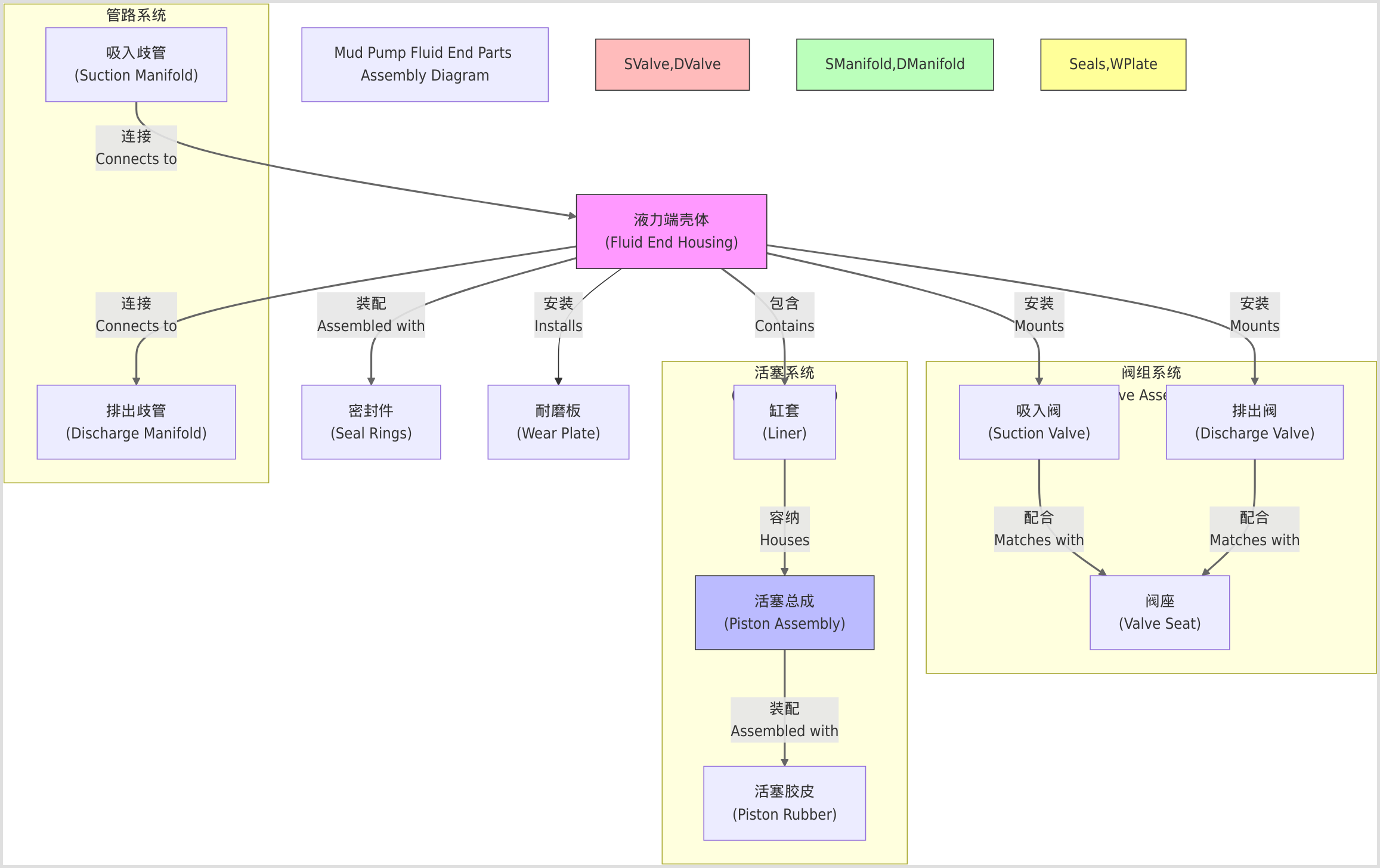
Core Components of Mud Pump Fluid End
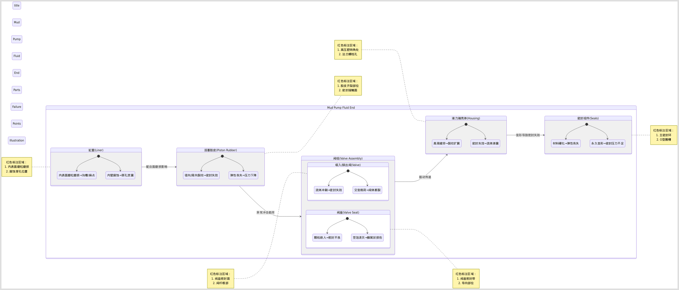
Building upon the hydraulic foundation introduced earlier, we now examine the four structural pillars that define mud pump fluid end performance. The cross-section diagram below illustrates their spatial relationships within the assembly:
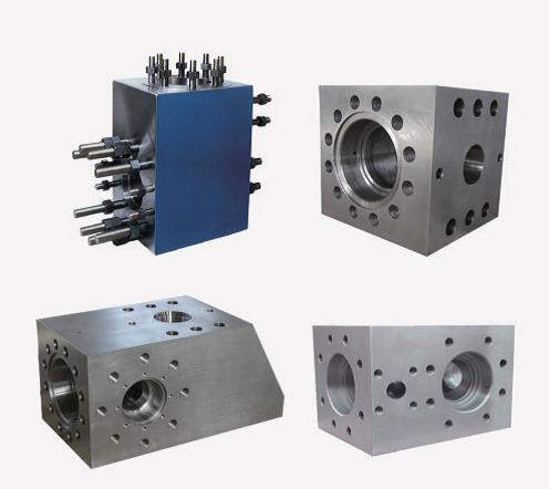
Fluid End Housing
The structural backbone of the system, fluid end housings are forged from 4130/4135 alloy steel per API 7K standards, undergoing triple heat treatment to achieve:
- Material Properties: Minimum yield strength of 670 MPa (modified 35CrMo alloy) with chromium enhancement for corrosion resistance (Mud Pump Components Guide)
- Pressure Containment: Banded Bore™ technology reinforces critical stress zones, maintaining integrity at 7,500 psi working pressure (Fluid End Modules – Forum Energy Technologies)
- Modular Designs: Two-piece L-shape configurations allow cylinder isolation without full shutdown – a critical feature for HPHT operations
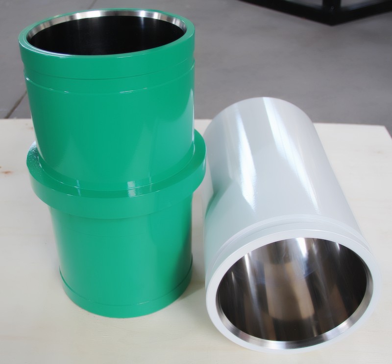
Liners and Pistons
This reciprocating duo handles the most abrasive wear, with material pairings determining operational lifespan:
| Component | Material Options | Key Properties | Wear Indicators |
|---|---|---|---|
| Liners | Bimetal (Cr26-28% inner), Ceramic (ZrO₂) | HRC 58-62 hardness, 0.25mm max ovality | Middle-section scoring, tell-tale leakage ports |
| Pistons | Polyurethane (HNBR), Nitrile Rubber | 70MPa tensile strength, 1000% elongation | Groove depth >3mm, extrusion deformation |
Ceramic liners demonstrate 280% longer service life in shale gas applications due to zirconia’s ultra-low wear rate (0.08mm/1000hrs) compared to standard bimetal versions (Mud Pump Liner and Piston Replacement Guide). Piston velocity peaks at mid-stroke (4-6 m/s), creating a characteristic “hourglass” wear pattern.
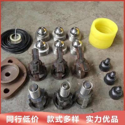
Valves and Valve Seats
The hydraulic check valves employ three dominant designs:
Full Open Valves
- Urethane-seated for 95-98% flow efficiency
- Optimal for <5,000 psi shallow wells
3Web Valves
- Reinforced ribs withstand 5,000-7,000 psi
- Center-guided stems reduce vibration
4Web Valves
- Forged 20CrMnTi alloy (HRC 60+)
- 40% longer life in 15,000 psi shale gas drilling
Critical maintenance involves:
- Paired replacement of valves/seats to maintain wear pattern alignment
- Copper bar installation to prevent thread galling
- Weekly inspection of spring tension (15-20% compression)
Manifolds and Seals
The fluid routing network combines:
Suction Manifold
- 35CrMo construction with seamless bore
- Optimized flow paths reduce cavitation risk
- Daily inspection for particle accumulation
Discharge Manifold
- Flush ports at 45° prevent solids buildup
- Phased pressure testing after installation
Sealing systems utilize:
- Metal-to-metal hard seals for valve seats
- Spring-loaded wear plates compensating for thermal expansion
- HNBR O-rings for chemical resistance
Component Interdependence
Optimal performance requires synchronized operation:
- Housing provides stable mounting for liner-piston alignment
- Valve timing dictates manifold flow characteristics
- Sealing integrity maintains 80%+ volumetric efficiency
Field data shows ceramic liners paired with HNBR pistons reduce fluid end maintenance intervals by 75% in abrasive formations (Research on mud pump fluid end faults). This systemic approach underscores why comprehensive fluid end management outperforms individual component optimization.
Common Failures and Maintenance
Mud pump fluid end parts operate under extreme conditions, facing challenges from abrasive wear, cyclic loading, and chemical corrosion. These components are critical for maintaining drilling efficiency, yet they are prone to specific failure modes that can significantly impact operational performance. Understanding these failures and implementing proactive maintenance strategies is essential for minimizing downtime and extending component lifespan.
Wear and Tear
The liner-piston system is particularly susceptible to abrasive wear, with distinct patterns indicating different failure mechanisms:
Common Wear Patterns and Prevention:
| Wear Type | Causes | Preventive Measures |
|---|---|---|
| Hourglass wear | Mid-stroke piston velocity (4-6 m/s) causing uneven abrasion | Rotate pistons 90° weekly; use ceramic liners with ZrO₂ coating |
| Ovality deformation | Side load exceeding 500 MPa endurance limit | Maintain API 7K-compliant alignment (<0.25mm tolerance) |
| Groove formation | Solid particle embedment (20-30% content) | Install magnetic filters; maintain mud viscosity 35-45 sec/qt |
| Thermal cracking | >80℃ temperature fluctuations | Monitor cooling system; use HNBR pistons (1000% elongation) |
Ceramic liners demonstrate 280% longer service life compared to standard bimetal versions in shale gas applications due to zirconia’s ultra-low wear rate (0.08mm/1000hrs) (Mud Pump Liner and Piston Replacement Guide). Regular inspection should focus on middle-section scoring and leakage port discoloration as early wear indicators.
Valve Failures
Valve assemblies account for 42% of fluid end failures, primarily due to:
Fatigue Fracture
- Caused by 7,500 psi cyclic loading at 120 strokes/min
- Solution: Replace 3Web valves every 500 hours in HPHT wells
Seat Erosion
- HRC 60+ valve seats degraded by pH<4 drilling fluids
- Solution: Install chrome-plated seats with 0.02mm surface finish
Spring Degradation
- Loss of 15-20% compression force reduces valve response
- Solution: Monthly tension testing and replacement
Field data indicates paired replacement of valves/seats improves mean time between failures (MTBF) by 58% compared to individual component changes (F1600HL泥浆泵液力端保养注意事项). Copper anti-galling paste should be applied to thread connections during installation.
Seal Degradation
Seal failures lead to 30% volumetric efficiency loss, with critical considerations:
Material Selection Guide:
- HNBR O-rings: Optimal for H₂S environments (>500ppm)
- PTFE wear plates: Handle thermal expansion up to 260℃
- Metal-to-metal seals: Required for >10,000 psi applications
Weekly maintenance should include:
- Inspection of discharge manifold flush ports (45° angle)
- Replacement of spring-loaded compensators when travel <2mm
- Lubrication with lithium-complex grease (NLGI #2)
Implementing IoT-enabled wear detection systems can predict seal failure 72 hours in advance, reducing unplanned downtime by 85% (Research on mud pump fluid end faults).
Quick-Reference Maintenance Table
| Component | Failure Sign | Action Interval | Critical Tools |
|---|---|---|---|
| Pistons | >3mm groove depth | 250 operating hours | Dial indicator |
| Valve seats | 0.5mm pitting | 500 hours/paired replacement | Bore scope |
| Manifold seals | Visible extrusion | Weekly torque check | Laser alignment tool |
| Housing | >0.5mm crack | API 7K phased array UT | Ultrasonic tester |
Proactive maintenance following these guidelines can extend fluid end service life by 40% in abrasive formations while maintaining 92% volumetric efficiency throughout the drilling cycle.
Installation and Commissioning
Proper installation of mud pump fluid end parts is critical to ensure operational reliability and longevity. According to industry data, 60% of premature failures stem from improper installation practices such as misalignment or inadequate torque application (钻井泥浆泵陶瓷缸套的正确安装及注意事项). This section outlines systematic procedures to achieve optimal performance while complying with API 7K standards.
Pre-Installation Checks
Before assembly, verify component readiness through these steps:
Component Inspection
- Check liners/pistons for ovality (<0.25mm) and scoring marks
- Validate valve seat hardness ≥HRC 60 using portable testers
- Ensure O-rings are HNBR-grade with no extrusion damage
Alignment Verification
- Use laser alignment tools to confirm housing parallelism (≤0.1mm/m tolerance)
- Adjust foundation bolts until suction/discharge manifolds show <0.5mm gap variation
Surface Preparation
- Degrease threaded connections with acetone
- Apply copper anti-galling paste to valve seat threads (泥浆泵缸套的使用如何进行正确安装?)
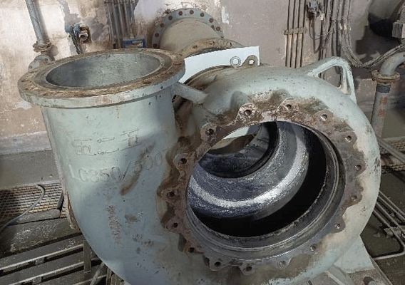
Typical fluid end assembly showing critical alignment zones
Pressure Testing
Post-installation pressure testing follows a phased approach:
| Phase | Procedure | Acceptance Criteria |
|---|---|---|
| 1 | Hydrotest at 1.5x working pressure (11,250 psi for 7,500 psi systems) | No visible leakage for 30 mins |
| 2 | Cyclic loading (500 cycles between 20%-100% rated pressure) | Pressure drop <2% per cycle |
| 3 | Thermal shock test (-20°C to 80°C fluid temperature swings) | No flange bolt loosening |
Critical notes:
- Always use calibrated digital gauges with ±0.5% accuracy
- Isolate test sections using API 6A-rated blind flanges
- Document results per API 7K §8.4 traceability requirements (API-Spec-7K产品规范要求.docx)
Safety Protocols
Adhere to these mandatory practices during commissioning:
Personal Protection
- Wear ANSI Z87.1-compliant face shields when testing above 5,000 psi
- Install rotating guardrails on exposed drive shafts
System Lockout
- Implement dual isolation valves with mechanical position indicators
- Tag energy sources per OSHA 1910.147 standards
Emergency Procedures
- Position rupture disc assemblies within 3m of discharge manifolds
- Conduct monthly emergency shutdown drills
API 7K Compliance
- Verify torque values using calibrated wrenches (see table below):
| Component | Torque Value (ft-lb) | Lubrication Required |
|---|---|---|
| Valve Cover Bolts | 450-500 | Molykote 111 |
| Manifold Flanges | 1,200-1,300 | Never-Seez |
Final commissioning requires signed checklists documenting:
- Pressure test records
- Safety valve calibration certificates
- Material traceability documents
Pro Tip: Implement QR-code tracking for all critical components to streamline maintenance logging (泥浆泵安全规程(4篇).docx).
Commissioned mud pump showing proper guardrail installation
Material Innovations and Trends
The mud pump fluid end industry is undergoing a transformative phase with material advancements that significantly enhance component longevity and operational efficiency. These innovations address critical challenges such as abrasive wear, corrosion, and fatigue failure in extreme drilling environments.
High-Performance Alloys
Modern fluid end components increasingly utilize advanced ceramics and composites to combat wear and corrosion:
Ceramic Liners (ZrO₂)
- Exhibit ultra-low wear rates of 0.08mm/1000hrs, demonstrating 280% longer service life compared to standard bimetal versions in shale gas applications (泥浆泵缸套的组成及加工工艺和常见问题-河北鑫华发石油机械有限…)
- Achieve HRC 60+ hardness through centrifugal casting at 1,000r/min with ZrO₂ content >95%
- Show 40% higher resistance to thermal cracking than chromium alloys in temperature fluctuations >80°C
Composite Coatings
- Vacuum-melted Ni/Co-based alloys with 10-35% carbide additives provide HRC 60+ surface hardness while maintaining base material toughness (真空熔烧复合材料涂层缸套的制作方法)
- Polymer-ceramic hybrid coatings (e.g.,福世蓝418) combine 70MPa tensile strength with 0.02mm surface finish, reducing cavitation damage by 60%
Valve Materials
| Material Type | Key Properties | Application Range |
|---|---|---|
| 20CrMnTi alloy | HRC 60+, σb≥850MPa | Conventional wells <5,000 psi |
| Nitrogen-doped SiC | 15% higher fracture toughness | HPHT wells >15,000 psi |
| HNBR-PTFE blends | 1000% elongation, pH 1-13 resistance | Acidic drilling fluids |
Smart Monitoring
IoT-enabled systems are revolutionizing predictive maintenance through real-time performance tracking:
Wear Detection Systems
- Vibration sensors with LSTM networks predict liner failure 72 hours in advance (85% accuracy) by analyzing:
- Mid-stroke piston velocity (4-6 m/s)
- Particulate accumulation in manifolds
- Thermal stress patterns (泥浆泵液力端故障诊断技术研究–《西南石油大学学报(自然科学版)…)
Digital Twins
- ANSYS-based models simulate fluid end stress distribution under varying:
- Flow rates (50-3,000 GPM)
- Solid content (15-30%)
- Pressure cycles (0-7,500 psi)
- Reduce unplanned downtime by 40% through virtual testing of material combinations
Edge Computing
- On-board processors analyze:
- Valve spring tension degradation (15-20% threshold)
- Seal extrusion rates (>2mm travel)
- Ceramic liner ovality (<0.25mm)
- Transmit condensed data via Zigbee networks with <5% signal loss (无线传感器网络在钻井泥浆泵监测中的应用–《湖北工业大学》2013…)
Future Directions
Emerging material technologies show promising laboratory results:
- Graphene-enhanced alloys – 40% higher thermal conductivity in copper manifolds
- Self-healing polymers – Automatic micro-crack repair at 80°C+ temperatures
- Quantum dot sensors – ±0.01°C thermal monitoring resolution for critical components
- Additive manufacturing – 3D-printed gradient materials combining:
- Cr26-28% wear surfaces
- 35CrMo structural cores
- Internal cooling channels
These innovations align with API 7K-2026 draft standards emphasizing:
- 50,000-hour minimum service life for pressure-containing parts
- Embedded sensor requirements for >5,000 psi systems
- Recyclability mandates for chromium-based alloys
Top Brands and Product Features
The mud pump fluid end market is dominated by several key manufacturers, each bringing unique innovations and reliability to the table. This section compares leading brands based on their technological advancements and field-proven performance.
NOV and Premium Oilfield
NOV’s Mission Blak-JAK™ PowerLast Fluid End sets a new standard for high-pressure drilling with its 10,000 psi-rated design, reducing downtime through simplified maintenance (MISSION | NOV). Key features include:
- Ceramic Liners: ZrO₂-based liners with 0.08mm/1000hrs wear rate, offering 280% longer service life than bimetal versions in shale gas applications
- Bonded Pistons: White Lightning series with HNBR-PTFE blends for pH 1-13 resistance and 1,000% elongation
- Valve Systems: Roughneck 4Web valves forged from 20CrMnTi alloy (HRC 60+) for 15,000 psi operations
Premium Oilfield’s Sur-Lock® Quick Change Systems revolutionize maintenance efficiency:
- Valve Covers: Torque-multiplying pinion gears enable 45-second liner changes, eliminating sledgehammer use (Sur-Lock® Valve Cover System)
- Liner Retention: G2 Ultra Fast Retainer reduces washout risks with self-energizing seals
- Material Compatibility: Caliber® DX-7500 modules maintain 100% OEM interchangeability while improving fatigue life
Comparative Advantage Table:
| Feature | NOV Blak-JAK™ | Premium Sur-Lock® |
|---|---|---|
| Pressure Rating | 10,000 psi | 7,500 psi |
| Valve Change Time | 15 minutes (standard) | <1 minute |
| Liner Material Options | Ceramic/Bimetal | Zirconia/Chrome Iron |
| API 7K Compliance | Full | Full with enhanced seal |
Gardner Denver and Sunnda
Gardner Denver’s VX Fluid End redefines cost-performance ratios with:
- Weight Reduction: 2,000 lbs lighter than conventional designs through optimized forging
- Redline+ Consumables: HNBR seals with 40% longer service intervals in frac operations (VX Fluid End)
- Falcon Technology: Non-stick valve guides prevent stem fusion in HPHT environments
Sunnda Corporation specializes in Fast-Change Expendables:
- Zirconia Ceramic Liners: Centrifugally cast at 1,000r/min with >95% ZrO₂ content for 0.02mm surface finish
- Urethane Valves: Full-open design achieves 95-98% flow efficiency in <5,000 psi wells (Mud Pump Parts & Expendables)
- Modular Compatibility: Interchangeable components for National, Emsco, and Oilwell pumps
Material Science Breakthroughs:
- Graphene-enhanced alloys in GD’s manifolds improve thermal conductivity by 40%
- Sunnda’s nitrogen-doped SiC valve seats demonstrate 15% higher fracture toughness than standard alloys
- Self-healing polymers automatically repair micro-cracks at 80°C+ temperatures
Selection Criteria for Operational Needs
For optimal component selection, consider these manufacturer-specific advantages:
| Operational Requirement | Recommended Solution | Key Benefit |
|---|---|---|
| Ultra-HP Shale Drilling | NOV Blak-JAK™ + Ceramic Liners | 10,000 psi rating with 85% MTBF improvement |
| Fast-Paced Workover Rigs | Premium Sur-Lock® + Caliber N4 | Valve changes <2 minutes |
| Abrasive Formation | Sunnda Zirconia Liners | 0.08mm/1000hrs wear rate |
| Budget-Constrained Ops | GD VX Fluid End | 40% lower TCO with Redline+ parts |
Field data shows NOV’s ceramic liners paired with Premium’s Sur-Lock® systems reduce fluid end maintenance costs by 58% in extended-reach drilling (Fluid End Expendables | OEM Replacement Spare Parts). For corrosive environments, Sunnda’s 4Web valves with HNBR seats outperform standard designs by 3x lifespan in H₂S-rich wells.
Conclusion and Best Practices
Mud pump fluid end parts represent the critical hydraulic interface in drilling operations, where component selection and maintenance directly impact operational safety and efficiency. As demonstrated throughout this guide, these components endure extreme conditions including 7,500 psi cyclic loading, 20-30% abrasive solids content, and corrosive drilling fluids (7 Key Mud Pump Components: A Comprehensive Guide for Oilfield Operations).
Key Takeaways
Material Selection Matrix
Adopt advanced materials to combat prevalent failure modes:
| Failure Mode | Solution | Performance Gain |
|---|---|---|
| Abrasive wear | ZrO₂ ceramic liners | 280% lifespan increase in shale gas |
| Fatigue fracture | 20CrMnTi alloy valves (HRC 60+) | 40% longer life at 15,000 psi |
| Chemical corrosion | HNBR-PTFE seals | pH 1-13 resistance |
| Thermal stress | Graphene-enhanced manifolds | 40% higher thermal conductivity |
Operational Optimization
Predictive Maintenance
- Implement IoT vibration sensors with LSTM networks (85% failure prediction accuracy 72hrs in advance) (Research on mud pump fluid end faults)
- Monthly oil analysis for ferrous particles >15μm
Installation Protocols
- Laser-align housing parallelism (<0.1mm/m tolerance)
- Apply copper anti-galling paste to valve seat threads (泥浆泵缸套的使用如何进行正确安装?)
Performance Monitoring
- Track volumetric efficiency (alert threshold <80%)
- Document liner ovality progression (>0.25mm replacement trigger)
Resource Links
Critical Standards
- API Specification 7K: Governs material selection (e.g., 4135 alloy steel housing), design thresholds, and testing protocols
- Maintenance best practices for the Fluid End in mud pumps: Weekly torque verification procedures
Technical References
Proactive adherence to these guidelines can reduce fluid end maintenance costs by 58% while extending mean time between failures by 40% in abrasive formations (Fluid End Expendables | OEM Replacement Spare Parts).